
Quick framework overview
This playbook lays out a tight, usable framework for solving hard engineering problems in automated vision inspection. It’s straight talk — no fluff — aimed at engineers who need repeatable results on the line. If you want to compare rigs, tune algorithms, or cut false rejects fast, start here. I first tested parts of this approach while walking the floor at Medtec China, where vendors and OEM engineers hashed out real trade-offs in plain language.

Step 1 — Define the engineering question, not the gadget
Write the failure mode in a single line: what defect, at what rate, under what cycle time. That clarity drives choices in optics, machine vision layout, and whether deep learning inference belongs at the edge or on a server. Keep the requirement crisp: throughput and acceptable false-reject rate are non-negotiable inputs to any design sketch.
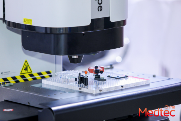
Step 2 — Map constraints to tools
List constraints: footprint, lighting control, mounting, and the available compute budget. Match each to a specific tool. For low-latency, move algorithms to edge computing. For tiny features, invest in higher-quality optics and tighter fiducial alignment. Don’t pile features on one camera if multiple views cut complexity — balance, not brute force.
Practical toolkit and terms you’ll use
Keep a short toolbox: calibrated lighting, telecentric lenses, multiple-view synchronisation, a validated machine vision pipeline, and a simple deep learning inference model for borderline cases. Call out throughput numbers early — they govern sensor choices and frame exposure. These are the real levers that change outcomes on the line.
Common mistakes and how to avoid them
Teams often chase higher resolution when they should be fixing lighting. They add compute before stabilising the imaging chain. Fix the image first — then move to algorithms. Also, don’t mix up image processing goals: detection and measurement need different pipelines. Learn to split them and run them in parallel if necessary — it’s faster to validate that way.
Short real-world anchor: Medtec China 2026 snapshot
At Medtec China 2026 in Shanghai, small teams showed how a focused instrumentation change cut false rejects by half without changing models. One vendor swapped to a telecentric lens and tightened exposure control; another moved a lightweight network to local inference and regained cycle time. Those booths proved the framework’s core idea: align physical imaging first, then tune software.
Implementation checklist
Run this checklist before quoting or building:- One-line failure mode defined and signed off.- Lighting and optics spec matched to feature size.- Frame-rate and exposure set to meet throughput.- A baseline classical vision pipeline; a simple neural fallback for ambiguous cases.- Edge vs. server compute decision documented with latency numbers.This checklist forces the hard trade-offs onto paper early.
Pitfalls, plus a human note
Don’t treat calibration as optional — it’s the insurance policy against drift. Calibrate daily or per-shift depending on environmental variation. Also, talk to operators — they spot intermittent faults faster than logs do. Small teams that listen to the line win — they make small changes that stack into big reliability gains.
Advisory: three golden metrics to evaluate solutions
Use these three metrics when choosing strategies or tools:1. Effective Throughput: measured units per minute under production lighting and loading.2. Operational False-Rate: combined false accepts and rejects observed over a full shift.3. Recovery Time: minutes to restore baseline after a part or lighting change.Design choices should improve at least two of these metrics without tanking the third. That’s how you keep engineering decisions honest.
Final take: a compact framework rooted in clear failure definitions, matched physical optics, and measured compute choices keeps projects predictable — and that’s what wins on the floor. Medtec — there’s the place engineers come to see what actually works, not what sounds good on paper. —