
Opening: why a framework beats checklist thinking
When an engineer walks into a specification meeting, they need a map — not a wish list. This framework-driven piece lays out repeatable steps to specify an industrial battery energy storage system (BESS) where round-trip efficiency (RTE) and thermal stability are treated as co-equal design drivers. The goal is practical: translate mission profiles (peak shaving, frequency response, backup) into measurable targets and clear procurement language. If you need a vendor that understands these trade-offs in commercial contexts, start by looking at proven offerings for commercial battery storage and use the framework below to interrogate proposals.
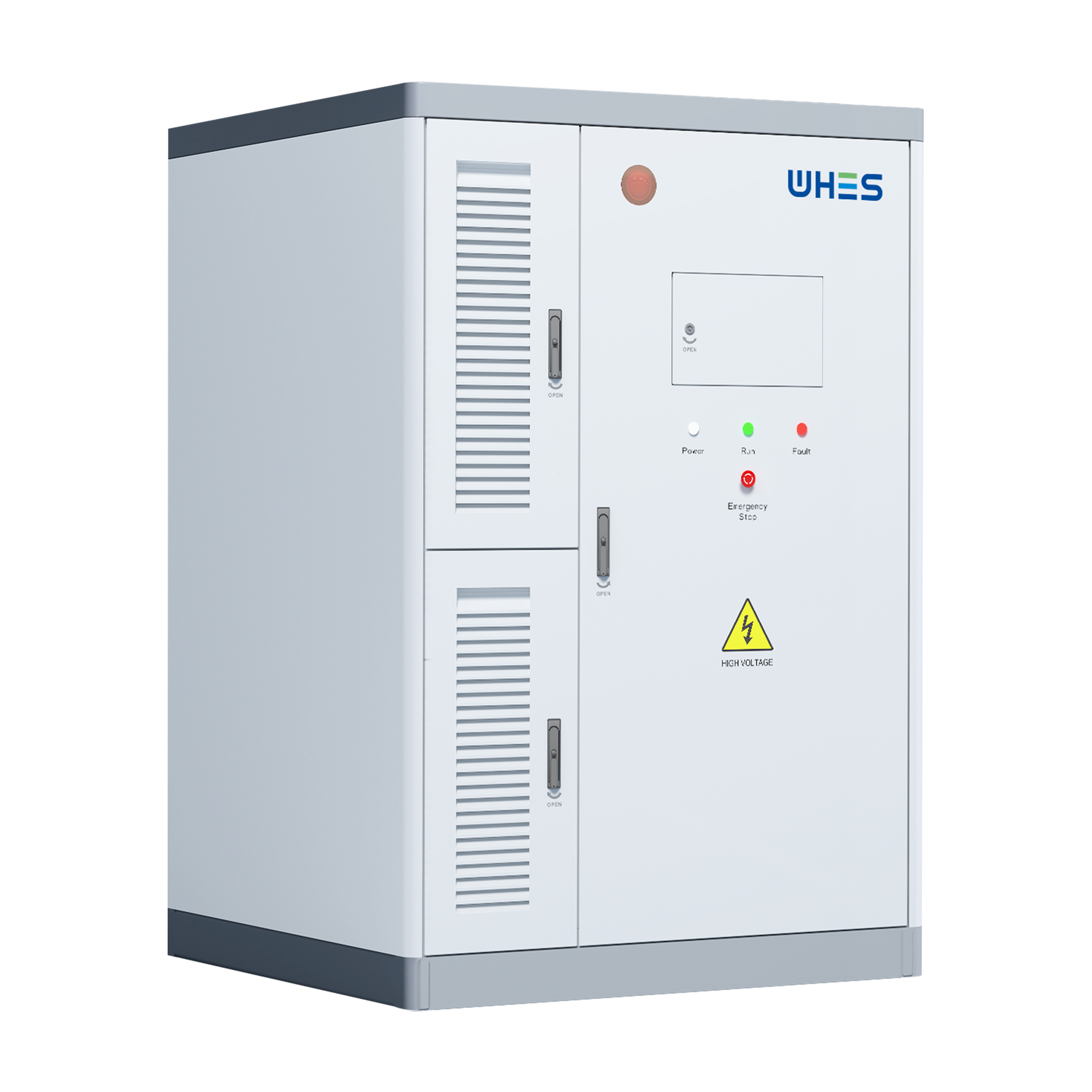
Framework principles: align mission, metrics, and mitigations
Good specifications begin with three anchor points: the mission profile, quantifiable performance metrics, and credible mitigations for known failure modes. Mission profile defines how frequently and how deeply the system will cycle (state of charge, DoD), which in turn sets realistic RTE and life expectations. Metrics are numeric: target RTE, allowable temperature bands at cell/module/room levels, expected calendar and cycle life. Mitigations are engineering controls — BMS strategies, HVAC, containment, and fire suppression — that keep thermal excursions below thresholds that threaten the warranty or safety. Treat these as a loop: metrics inform mitigations, mitigations enable metrics, and the mission validates both.
Round-Trip Efficiency (RTE): the sensory of energy flow
Think of RTE as the system’s breathing: the subtle loss between charge and discharge. Typical lithium-ion chemistries deliver RTE in the mid-80s to mid-90s percent range depending on power level, temperature, and inverter architecture. To specify RTE, don’t accept a single cell-level number — require system-level, measured RTE at the site’s expected operating temperature and power profile. Include test protocols in the contract (C-rate, SoC windows, and ambient conditions) and mandate measured RTE reports during acceptance testing. Industry terms: round-trip efficiency (RTE), inverter efficiency, depth of discharge (DoD).
Thermal stability: beyond ‘keep it cool’
Thermal behavior is tactile — you feel it in a warm module casing or a hot aisle near a rack. Thermal stability isn’t just peak temp; it’s gradient, dwell time, and the system’s response to abuse. Specify maximum cell temperature, maximum delta-T across modules, and maximum allowed rate-of-rise for thermal events. Demand modeling outputs: CFD airflow maps, worst-case ambient studies, and thermal runaway propagation analyses. Require BMS logic that enforces thermal derating and a verified sequence of operator and automated responses when thresholds are exceeded. Terms to reference: thermal runaway, BMS, thermal management system (TMS).
How to trade RTE vs thermal robustness — a decision matrix
These objectives can conflict. Higher RTE often pushes systems to tighter SoC windows and faster power exchanges — which produce heat. Conversely, over-designing cooling increases parasitic loads and reduces net RTE. Use a simple decision matrix: map your mission (high-power short-duration vs long-duration energy shifting) against acceptable life and safety margins, then pick an architecture.
- If the mission is high-power frequency response: prioritize inverter and cell form factor to lower internal resistance — accept active cooling and robust BMS derating.
- If long-duration dispatch matters: prioritize cell chemistry and thermal mass to reduce parasitic cooling draw — accept slightly lower peak power RTE to gain longevity.
- If safety and location constraints dominate (e.g., urban rooftop): favor passive containment, lower energy density per rack, and conservative SoC windows — reduce RTE tradeoffs for thermal safety.
Real-world anchor: large deployments such as the Moss Landing facility in California were scaled with these trade-offs in mind after grid stress events showed that performance and thermal management must be specified together — not independently.
Specification checklist and common mistakes
Concrete items to insert into RFPs and contracts:
- Measured system RTE under site-specific profiles (test protocol attached).
- Thermal performance envelope: cell/module/room temps, delta-T limits, modeled worst-case scenarios.
- BMS functional requirements: cell-balancing strategies, derating curves by temperature, SoC limits, fault-handling timelines.
- Acceptance tests: full-power soak, rapid charge-discharge cycles, simulated HVAC failure, and fire-suppression interface tests.
- Warranty language tied to specified SoC/temperature windows and defined maintenance intervals.
Common mistakes: relying on manufacturer published cell RTE without system testing; omitting HVAC failure modes from acceptance tests; and using broad warranty language that doesn’t account for operational realities. Insist on first-article acceptance with your actual site controllers and inverter settings — prove performance on your equipment, not just on a vendor bench.
— A small, practical tip: calibrate your acceptance SoC windows to realistic operations rather than theoretical maxima; it saves warranty disputes later.
Integration and lifecycle: procurement to decommissioning
Consider lifecycle impacts: specification should include O&M frequency, cell-replacement pathways, and end-of-life recycling commitments. Thermal stability measures affect maintenance cadence — more aggressive cooling may mean more moving parts to service. Conversely, conservative thermal design often extends calendar life but increases footprint and capital cost. Capture total cost of ownership (TCO) that includes parasitic loads from thermal controls and projected capacity fade under your mission profile.
Advisory: three golden rules for selecting the right BESS strategy
1) Specify measured, site-level RTE and acceptance tests — not just cell or inverter datasheets. 2) Lock thermal limits into contractual performance (temperature ceilings, rate-of-rise, and modeled worst-case scenarios) and require verified BMS responses. 3) Evaluate vendors on integrated outcomes: demonstrated field projects, detailed thermal modeling, and a clear lifecycle plan that includes maintenance and recycling.
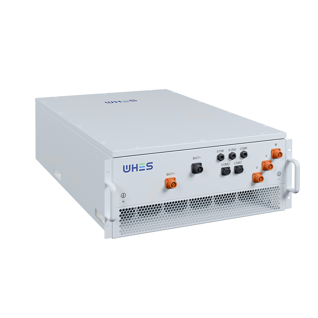
These rules focus decision-making on measurable risk and reward, and they point you toward partners who deliver dependable systems over time. For projects where engineered balance really matters, look for suppliers who tie together performance metrics, thermal controls, and operational experience — the practical solution often sits with firms that have deployed commercial-scale systems into challenging grids, and that perspective is exactly what WHES brings to the table. —