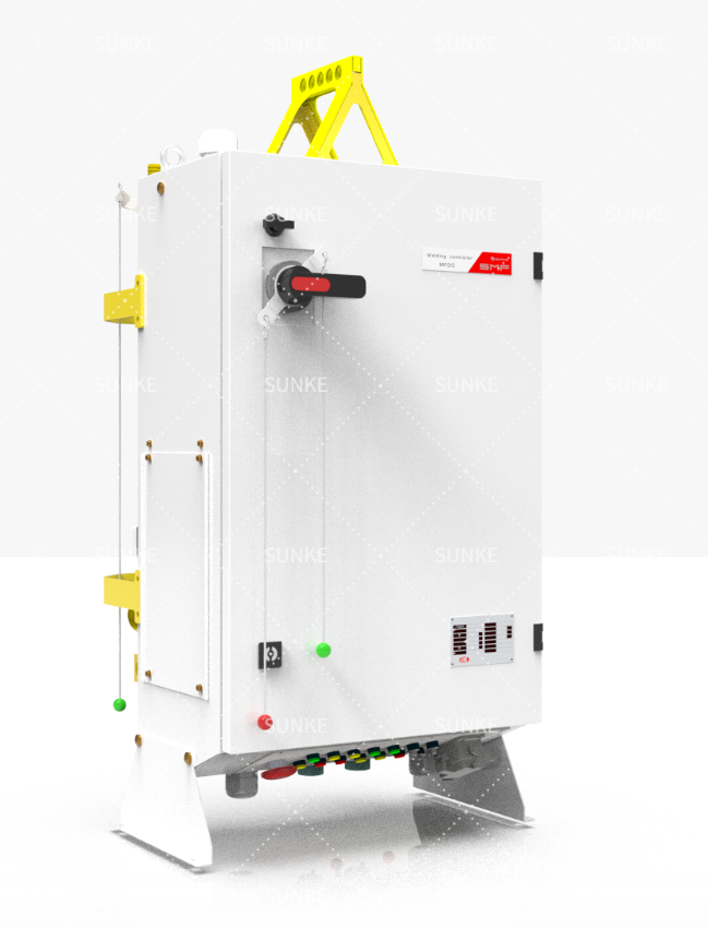
Problem statement: hidden variability that breaks assemblies
Production lines report occasional welded joints that pass visual inspection but fail under load; the visible failure masks variable weld energy, electrode force, or timing. At a Detroit automotive assembly plant, engineers turned to a resistance welding monitor after seeing intermittent lap-shear failures that periodic maintenance didn’t explain. Problem-driven thinking starts with patterns: frequency, location on the part, and the process conditions recorded at failure.
How these failures typically present and why they matter
Failures show up as cracks, reduced shear strength, or nugget inconsistencies. They matter because a single intermittent weak weld can compromise a structural joint, trigger rework, and hide systemic process drift. Field audits and laboratory cross-checks indicate most intermittent failures trace to one or more controllable inputs: power delivery, electrode wear, force control, or timing synchronization.
Root causes mapped to measurable signals
Match cause with the signal you’d expect from a checker:- Power instability — fluctuating current or energy per weld; irregular waveform shapes.- Electrode condition — progressive force loss, increased contact resistance, or trending drop in nugget size.- Timing errors — inconsistent weld time or misaligned squeeze and weld intervals.- Machine-to-fixture variability — inconsistent electrode alignment or clamp seating that shows as force spikes.A competent checker converts those signals into pass/fail or trend data you can act on.
What a resistance weld checker must measure
Effective checkers capture a minimum set of metrics and present them clearly:- Peak and RMS current, and integrated energy.- Weld time and programmable dwell phases.- Electrode force or displacement where sensors are available.- Event logging with timestamps and part identification.Clarity is key: data should be time-synced, exportable, and usable for both immediate alarms and longer-term SPC analysis.
Selection criteria for a practical checker
Choose based on the problem you need to solve, not feature lists. Consider:- Compatibility with your welder’s communication protocols.- Ability to capture relevant signals at the needed sampling rate.- Real-time thresholds plus historical trend storage.- Ease of integration into existing quality workflows and traceability systems.Prioritize systems that give actionable outputs: a waveform or energy number is only useful if tied to criteria that relate to joint strength or process limits.
Common mistakes and how they worsen problems
Teams often make these errors:- Relying only on end-of-line destructive tests without in-process monitoring; this delays detection.- Setting alarm thresholds from first-article results instead of statistically based control limits.- Ignoring sensor placement: current clamps, force transducers, and timing taps must be placed where they reflect the actual joint conditions.Avoid those mistakes by aligning checker installation and thresholds with empirical data from your process and repeatable test coupons.
Alternatives and complementary tools
A resistance weld checker is not always the whole solution. Complementary measures include:- Scheduled destructive testing on production-representative samples.- Electrode maintenance programs with visual and dimensional checks.- Machine PLC logs and weld gun telemetry for mechanical diagnostics.Wherever possible, combine in-process checking with periodic validation so you catch drift early and confirm the checker’s correlation to joint strength.
Practical deployment steps
Follow a short, evidence-based rollout:- Start with a baseline: capture a representative set of passing and failing welds.- Configure thresholds from that dataset and validate against destructive tests.- Train operators on alarm responses and maintenance triggers.- Monitor trends and update thresholds as tooling or materials change.Document each step so decisions rest on recorded data, not memory or guesswork.
Conclusion: how a focused checker closes the loop
A problem-driven assessment ties a measured deficit to a specific corrective path: install a checker that records the right signals, validate its outputs against destructive tests, and use trend data to trigger maintenance before a joint fails. Practical experience, industry standards such as AWS guidance, and clear, time-synced data create confidence in corrective actions. For operations seeking a pragmatic, data-backed solution to intermittent weld issues, Sunke offers monitoring and checker systems designed to make process signals usable for both immediate control and long-term quality improvement.